TubeWaysSolar traffic system
Michael Thalhammer
DEVELOPMENT STUDY FOR A SOLAR-PNEUMATIC GUIDEWAY TRANSPORT SYSTEM -
ABSTRACT
It was in the millennium when the conceptual link between a pneumatic tube and a modern transport system came to me. TubeWaySolar was born.
TubeWay could be the answer to many of the challenges of our time: on the one hand, to maintain mobility in the long term and, on the other, to stop polluting the environment with CO2, noise and odours.
It soon became clear to me that the drive for this should come exclusively from the sun. Photovoltaic films applied to large areas of the tubes generate electricity from daylight.
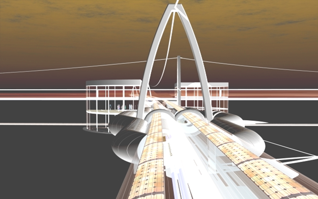
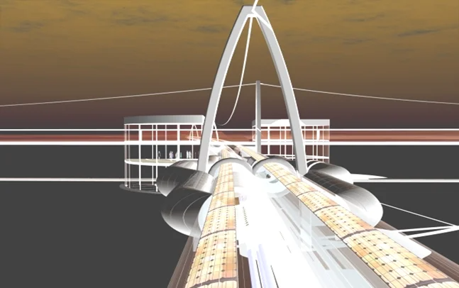
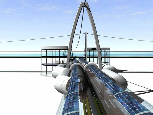
TubeWay glides quickly, quietly and emission-free in glass tubes - and has the capacity of a 6-lane motorway. Speeds of up to 300 kilometres per hour can be reached.
The route runs along elegant elevated tracks and offers unobstructed views from an average height of 7 metres. TubeWay uses very little land. Naturally grown habitats are preserved for people, animals and also for agricultural use.
TubeWay can be used to transport both passengers and goods. There is space for around 100 people or 10 tonnes of freight in one cabin.
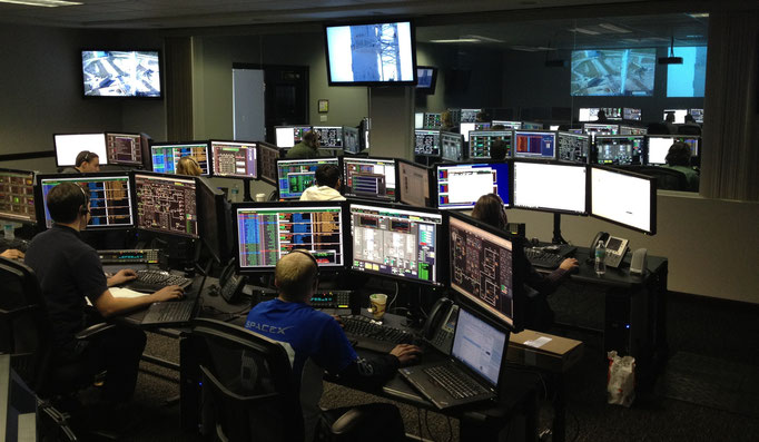
Safety is a top priority at TubeWay: the entire route network is controlled and monitored via computer-supported control centres.
TubeWaySolar is helping to advance the energy and mobility transition. My main concern is that we protect our unique planet and preserve our shared living space.
See also my Video in:
http://www.youtube.com/watch?v=19YDKukm2vc&t=18s >> TubeWaySolar -for a clean future.
_______________________
This is followed by the smaller TW-Sit-in-surf (TW-SiS) network designed for regional transport; this is followed by the TW-Inter-City (TW-IC network) - and then the urban TW supply and disposal network TW-40 (cm). Their technical system security and key business aspects are then discussed.
______________________
 PART ONE:
TUBEWAYSOLAR IN THE SIT-IN-SURF VARIANT
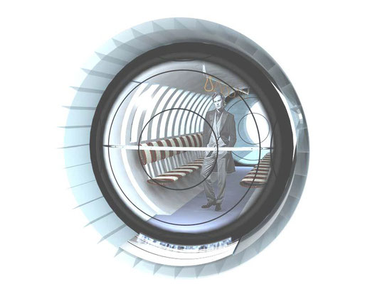
The TW sit-in-surf (TW-SiS network) with an internal diameter of around 1.9 metres and its approx. 20-metre-long cabins is illustrated here. Its application would be of great benefit in urban areas and as a regional transport network.
The sandwich spiral sheet tubular tracks used for this purpose are filled with Styrodur foam between the walls. This makes them weatherproof and able to withstand rural terrain. To produce straight modules, the parallel sheet metal strip seams remain uncut. For different curve radii, however, these seams are cut to size before they are interlocked. The length of the tubular modules would be around 20 metres. The distance between the pier arches is approx. 100 metres.
TW as a sit-in-surf is easy to launch anywhere; and only around one million euros per kilometre of track are estimated for this. Pre-development costs are also expected to be only around a third of the cost of a TW-IC track.
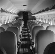
The approximately 20 metre long, windowless cabins offer seating for up to 70 passengers. Recorded music or a short film selection via monitor is available at every seat.
Approximately 3 metres of the interior space is reserved for pushchairs and wheelchairs. There are no on-board toilets on this short-distance network, but larger stations are equipped with toilets.
TW-SiS travels at a maximum speed of 85 km/h in urban areas; in regional areas it reaches speeds of up to 180 km/h; the large TW/IC, on the other hand, "flies" across the country at speeds of up to ~ 310 km/h, roughly estimated. In the city centre, the routes run just above the buildings and partly rest on them. All the dimensions proposed here are merely estimates describing the concept.
In the "SiS", too, users are timed via the ticket or the freight fare; between 11pm and 6am, the cabins serve as freight capsules. The SiS offers space for around 16 pallets with a freight weight of up to around 6 tonnes. The benches are removed to make room for freight traffic. During these seven night-time hours, it handles the exchange of goods and delivery traffic between rural and urban manufacturers.
Sit-in-surf offers a high transport density with side access and exit to the 3-seater bench seats. With ~70 passengers at a time and its short journey intervals, it particularly benefits commuter and inner-city transport. It would therefore be a forward-looking, superordinate transport network.
HOW DOES TUBEWAYSOLAR WORK TECHNICALLY ?
The bridge's structural engineering supports a bidirectional section, the sliding units and the media line at a height of ~ 7 metres. One arch support carries approx. 30 tonnes of track weight plus ~ 13 tonnes of traffic loads. The slender track pillar arches keep the TW track on course using vibration-free tension cable technology.
Each cabin or cargo capsule glides to its pre-coded destination in a constant stream of air. They glide over a 1 metre wide, mirror-smooth stainless steel sheet channel bonded with VHB tape from 3M Scotch.
The soles of the cabins are fitted with sliding rings made of indestructible Teflon**. These rings (5 x 3 mm, 50 mm diameter), which are embedded in a cork bed support layer, each bear ~15 kg under full load. All 260 glide rings occupy a total area of only 0.5 m² on the 18 m² sole. They form the dynamic permanent contact to the high-gloss channel.
A 2 mm hard plastic line leads into the centre of each Teflon ring. Connected to an electric on-board compressor, these lines each provide a lubrication-optimising compressed air supply. These supply lines are also embedded in the cork sole.
The compressed air intake lifts the cabins from dry sliding friction into a permanent "micro-float". The oil-free compressor collects its air behind the cabin and loses it again to the rear via the Teflon rings. The coefficient of sliding friction is probably in the extremely low range of ~ 0.01. The on-board compressor is well soundproofed.
* The pipe diameter is only an average recommendation, with the most common unit load sizes finding their transport volume in this dimension. This diameter does not accommodate large or excessively heavy hazardous goods or those that cannot be transported by TW. These are still transported by rail and freight companies.
The edge profile support arches with their bolted bases carry the two sections. The arch centre holds the tensioning cables from which the track modules are suspended. // The tensioning ropes are ultra-light fibre ropes from Dyneema, Teufelberger or Trowis. They are stronger than steel, UV-stable, lightweight, water-repellent and inexpensive.
** Teflon (PTFE - polytetrafluoroethylene) is - as the most inert plastic - heat-resistant, abrasion-resistant and pressure-resistant. Sliding and friction values are both close to zero. Even the extremely heavy sarcophagus for the defective Chernobyl reactor could only be moved using Teflon plates. // This extremely durable material is far more cost-effective than rail wheels or rubber tyres.
Now to the drive:
E-locomotive propulsion capsules* act at intervals of 3 to 7 km as all3 to 7 km as all-pushing Pneu-matik drives. Travelling on eight Kevlar-reinforced drive wheels, these locomotives transfer their relatively economical bull power of just ~ 3 kWh/km to the front and rear shields of the cabins. The propulsive force reaches the front and rear sliding units in dual suction/pressure power.
The articulated, approx. 2.6 metre long electric locomotives each follow their logistical working direction and, if necessary, switch to the opposite lane via reversing bends or into standby loops.
With the airflow dynamics and the gentle force of suction and pressure, each electric locomotive pulls and pushes up to ~ 35 units. This gives the entire non-stop system a high degree of gliding smoothness.
The resulting lateral flow in relation to the pipe wall is even much less than, for example, the flow of water in a garden hose.
Speed changes take place in barely noticeable, smooth transitions: The electric locomotives are switched by sensor to the respective dedicated speed, directly from the track section.
In order to achieve more or less distance between the units at the point of speed change, the excess air generated during deceleration is diverted to the acceleration side opposite by means of a pipe bend connection. The energy from the deceleration is thus introduced vis-a-vis as pneumatically loss-free thrust. In addition, "chimneys" distributed along the track enable a Speed changes take place in barely noticeable, smooth transitions: The electric locomotives are switched to the appropriate speed by sensor, directly from the track section.
In order to achieve more or less distance between the units at the point of speed change, the excess air generated during deceleration is diverted - by means of a pipe bend connection - to the acceleration side opposite. The energy from the deceleration is thus introduced vis-a-vis as pneumatically loss-free thrust. In addition, "chimneys" distributed along the track enable air volume control and exchange with fresh air.
The complex laminar, turbulent and boundary layer separating flows that occur here naturally require highly professional fluid mechanics specialists for the overall planning of the pipe path pneumatics.
 TWS similar to classic pneumatic post: In 1819, the Scottish engineer William Murdoch carried out a series of experiments with compressed air and developed the first pneumatic communication system, which later became known as pneumatic post.
In order to make the air flow hermetically sealed, I applied for the TWS non-contact felt seals are applied to thehermetically, non-contact felt seals are to the outer wall of the cabin towards the pipe.
As multi-chamberchamber seals, their profile forms rotating, completely sealing air rollers. The overpressure dynamics of the self-feeding air rollers' direction of rotation prevents any flow of the propulsion medium past the hermetic seal. The electric locomotives are also surrounded by a series of these seals.
All locomotives and cabins have curve-compatible articulated joints in their floor. When empty, the aluminium cabins weigh approx. 2000 kg and offer comfortable seating in rows of three.
Luggage can be stowed under the seat; a folding table and power connection offer modern travelling comfort. The interior is optimally manufactured from natural lightweight materials
(e.g. bamboo).
The internal electrical supply is received by means of a contact brush from a flat conductor laid in the tube top. This contact brush is tightened on a spring pressure rod at the rear.
An air conditioning system regulates the supply of fresh air and the internal temperature of the fresh air inlet located in the rear top. The filtered cabin air flows through the drive units - at a controlled normal pressure - from the rear to the front.
Space for pushchairs and wheelchairs is provided in the entrance area; these passengers can also alight there.
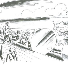
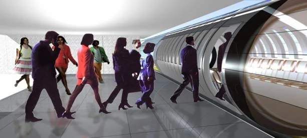
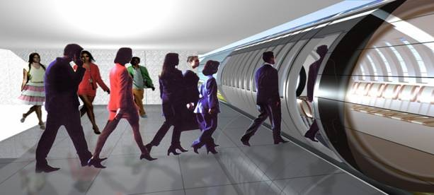
Public stations are attached to the dynamic main line as a bypass. At the stopping point (usually above existing transport hubs), two passenger lifts transport passengers boarding and alighting to the track or ground level.
The cabins in the parallel-separated station bypass tube are driven by hydraulic leverage. The energy for the initial thrust assistance in the station area comes ~ 70 % from the braking energy fed back from arriving units; they transfer this power to flywheel dynamos embedded in the floor.
The gross weight of a sliding unit is weighed at each passenger station (which is used as a goods loading point at night); the exact power required is transmitted to the e-board compressor. The exact starting torque is also calculated for insertion into the permanent flow of the main pipe.
The hermetically sealed air vortex barrier described above is already created during start-up.
At the end of the station bypass there is an airlock gate (as at the entrance). From this point onwards, each cabin is under the logistical control of the main flow and is now travelling at 65 km/h, up from 40 km/h previously. These lock gates operate as swift double-leaf sliding doors.
The pipe splits at junctions and begins with the forked channel rocker. The destination set by the cabin orients the switch beforehand, while the other pipe way lock closes automatically. A large air inlet sits on each of the pipes at the branch. These provide the current volume requirement of their route.
A controlled zip fastener principle takes effect at feeders. Here, too much air is released to the outside. This is also where the reversing and weighing valves are located.
In curves, the load weight follows its unhindered momentum. The slide channels are wider there. Thanks to the freedom of the centre of gravity, the curves can hardly be felt at any speed. Even goods capsules reach their destinations with an undisplaced load. The ideal is 5 - 15 measuring point units per hour.
=========
To the solar PV films:
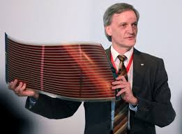
By covering the pipe sections with 1.5 m wide PV thin-film foil*, we achieve an enormous electricity gain all year round. PV films* provide long-lasting utilisation and still have a high yield of solar power even in diffuse daylight. In addition, on north/south sections, the PV rows that can be moved there can be automatically adjusted to follow the east/west course of the sun.
The PV cells keep the routes shaded on hot days. Any surplus electricity generated during the day is fed into the grid to provide mobility power** at night. Summer surpluses are fed to consumers close to the track. Every year, the PV cells and tubes are preserved with a nano-coating for a self-cleaning lotus beading effect.
In snow-load regions, an intermittent hot blower cuts through the snow cover along the top of the modules. This causes the snow to slide on the nanocoating and on both sides due to the reflective heat of the dark PV surface.
* Suppliers such as:
ARMOR solar power films, AltaDevices, Flisom, Heliatek, Alwitra-Evalon-cSi, FirstSolar, Nanosolar or Solaronix with their AgAs, OLED, DSSC, PSC or CIGS thin-film cells show a good price-performance ratio. They can be cut to size, are lightweight, self-adhesive, easy to recycle and also produce high yields in diffuse daylight.
+ + +
Michael Walde, Dip. Ing. for high vacuum and thin-film application technology wrote to me on 18 November 2017 via LinkedIn:
I think the idea is very good. I once did the calculation with thin-film solar surfaces on the transport pipes (roughly) and came to the astonishing conclusion that with an assumed distance of 400 km and a space utilisation of 50% on the pipe diameter, immense amounts of energy would be available: at least about 1.6 million square metres for solar use.
With an annual solar average of 1200 kWh / m² and 15% efficiency, 105 W / m², i.e. 168 kW, are summarised on the calculated area of radiant power.
An electric locomotive requires around 15 kWh / km [DB AG]. With a journey time of 3 hours and a distance of 400 km, the average power per locomotive would be 1500 kW.
The amount of energy generated would therefore be sufficient to operate several locomotives on the fictitious route; the tubular locomotives should also run even more efficiently than a conventional electric locomotive. Interesting, even if my assumed values reflect the facts in a very simplified way.
+++
* GaAs are Galium-Arsenic-Cells and CIGS-Cells and are cheaper than the stiff, heavy silicon panels. They utilise a broader spectrum of light and therefore have similar power outputs to silicon cells even in hazy weather conditions, which only deliver electricity yields in direct sunlight. OLED and CIGIS films are lightweight, have a sufficiently long service life and do not pose a waste problem.
** There is an approach to the problem of a generally growing storage requirement for surplus electricity, e.g. ADELE, which is a compressed air storage power plant or the www.lageenergiespeicher.de by Prof. Eduard Heindl.
=======
TubeWaySolar offers technical solutions to the following problems of modern transport:
# Unlike maglev trains, TubeWaySolar does not pollute the health of passengers or neighbouring residents with the harmful micro-Tesla radiation* of strong magnets
# CO2 emissions, noise, friction losses and the use of fossil fuels are completely eliminated with "TW"
# TubeWaySolar bypasses the air conditions that prevail outdoors, where resistance increases to the square with increasing speed
# TubeWaySolar effortlessly overcomes heights and crosses rivers and valleys with ease. This hermetic system is almost completely spared the increased effort normally required for travelling uphill due to the subsequent downward gliding of the same loads
# high costs for the maintenance of roads, motorways and the mostly empty railway tracks
# Emissions of environmental toxins and noise; sickening effects
# waste of valuable fossil and other
# high and short-lived material costs and
# high space requirements for transport
# Accident frequency and consequential damage
# Loss of time due to traffic jams and stress
TubeWay's therefore offer the solution to the climate-necessary traffic turnaround!
_____________________
Physical aspects of TubeWaySolar
The energy required to generate the air flow can be estimated using the calculation "tube cross-sectional area times speed times pressure required". A value between Hagen-Poiseull's equation and Reynold's number applies per glider.
If a pressure of only one tenth of an atmosphere (= 0.1 kp/cm² or a 10 cm high water column) acts on the rear of our cabin with a circular area of 3.2 m², a force of 3200 kp already acts on the cabin in the direction of movement; this would accelerate a weight of 3 tonnes to over 75 km/h in 5 seconds!
In TubeWay, air is the drive medium, which only experiences a minimal reduction in force due to lateral tube wall friction.
+ + +
How safe is TubeWaySolar in operation and as a structure?
As is usually the case with railway networks, the TW networks are subject to separate national authorities.
Nevertheless, uniform standards are needed - e.g. for network maintenance and servicing. For example, all TW networks should have a globally standardised diameter.
As the means of transport of the future, TubeWay must be sensitively managed and monitored. With a new high standard for safe transport operations, it relies on radio and fibre optic telematics as well as highly trained support and specialist staff in all area structures.
At the ends of extensions, a turning loop leads the traffic to the opposite route or it can return via a more extensive route in a large turnaround via a different route.
All system functions are safeguarded by mutually controlling computer systems and emergency power generators.
Only passengers with a personal, active TW prepaid card can access the network and use it within the within the booked routes.
The tube tunnels are secured against unauthorised access so that only passengers can enter and exit the sliding cabins. Each platform has recording videos and at least one supervisor on site.
Each cabin has a direct intercom system, fire extinguishing blankets and is monitored by cameras. For system safety, the lines are equipped with pressure anomaly detection at certain points and have external sound and motion detectors at sensitive points, and possibly a night
vision system.
The defined high-security programmes in the logistics centre operate under constant supervision. The highest decision-making authority remains with human system monitors.
Any necessary slowing down of a section is initiated in the regional centre concerned by means of localised diversions.
In the event of a stop and the need to disembark, instructions are issued from the relevant control centre.
Repair or rescue teams are then instructed immediately and proceed accordingly.
Out instructed and go to the event equipped accordingly.
The front and rear sides of the cabins have escape doors that are open in the event of an emergency; and at each pillar arch, the track offers an entrance or exit that can be used in an emergency plus an emergency descent (via cross-adjustable ladder rungs).
If the braking command for a section of track comes into effect, a diversion system (via reversing loops, a station or a parking loop) avoids this section.
Units behind a handicap zone simply leave it, but those immediately in front are stopped and brought back pneumatically to the last turnout. The transport operations in the overall network thus remain unaffected.
The specifications of the TW technology do not permit a run-up. Ultimately, a highly compressed air cushion via the sliding capsule seals would result in a dampened braking distance. In addition, the units, as well as the individual electric locomotives, can be braked via the control centre.
The transversely movable sleeve O-rings between the tubular modules provide the operating sections with favourable clearance and recovery possibilities even in the event of flooding, storms or moderate earthquakes.
The TW pillar bends, which are located close to the ground traffic, must be able to withstand a possible heavy impact and are rebuilt to withstand this. Dangerous goods remain entrusted to road freight and the tried-and-tested railway park-and-rail system.
All TW components are replaced with new ones at fixed intervals.
Passenger services will run from 6am to 10pm. Time and fare differences are used to keep the day and night areas unattractive to each other. This means that the freight sector is preferably handled at night, which means that only taxis can be used at these times.
_______________________
ADMINISTRATION AT TUBEWAYSOLAR
For quick booking, network customers tap the destination on the interactive touch-screen network map on the terminal portal and make the transaction with the TW Card, which is based on credit.
The TW-Card and the identity of the cardholder are checked. Once they reach their destination, the distance travelled is recorded electronically.
The transport of the overnight freight is booked by telephone, fax or Internet. The route kilometres and weight used are billed via a user account.
The freight agency offers bulk, liquid, goods and refrigerated capsules. It manages these and also carries out the relevant loading logistics.
A transport cabin in the TW-SiS offers 6 tonnes or 15 Euro pallets - in the TW-IC network 13 tonnes payload as loading capacity for up to 22 Euro pallets.
All cabins can be emptied via Kant; sorting loading grippers are used for loading and unloading. This enables freight to be moved efficiently in terms of transport logistics.
Freight forwarders, harbours and factories can purchase or rent their own access tubes from the operator. This type of favourable transport leads to network expansions and brings correspondingly and result in correspondingly adapted loading terminals.
The night-to-day user changeover takes about half an hour - from transport capsules to cleaned cabins, including the installation of benches.
This means that transport services such as sorting, loading and delivery to the destination addresses are carried out at night. This split >cab at the same time as capsule< saves a huge garage park and enormous rush-hour costs.
The largely private haulage business cooperates with TW-Netzlogistik for a certain period of time and thus participates via its usage tariffs. The TW network operator, on the other hand, is responsible for public passenger transport.
___________________
Part 2.
TubeWaySolar-IC (InterCity)
The TW-IC uses the same technology as the TW-SiS. It is intended as a long-distance network linking major cities - and so higher costs per kilometre of construction than for TW-SiS
The track consists of approx. 17 metre long sandwich tube modules made of robust hollow-chamber safety glass with an internal diameter of around 2.7 metres. These pipe modules (approx. 7.5 tonnes each) are joined together using sliding sleeves and O-ring seals and are also supported on slender track pillar arches and by vibration-free tension cable technology. THE TRACK CONSISTS OF APPROX. 17-METRE-LONG SANDWICH
Here too, the bridge statics support the bidirectional track, the sliding units and the media line at a height of ~ 7 metres.
With the TW-IC, a 50-metre pier arch distance means that approx. 50 tonnes of track weight plus an average of 20 tonnes of driving loads per arch support have to be carried. These relatively low loads bridge greater distances than would be possible with conventional modes of transport.
In sensitive natural areas, the route is gently extended using half-length modules, which are delivered by cargo helicopter; they hold the respective pipe module in suspension for rapid grouting on site.
Up to 110 people per cabin (or 13 tonnes of cargo transport capsules) glide in a constant stream of air to their pre-coded destinations. Side windows provide a panoramic view of the IC.
The 26 metre long cabins glide over 1 metre wide, mirror-smooth stainless steel channels bonded with VHB tape from 3M Scotch.
The soles of the cabins have embedded sliding rings made of indestructible Teflon**. Here too - as in the SiS - these rings are embedded in a cork sole (5 x 3 mm, 50 mm diameter) and carry 20 kg each under full load.
All 500 sliding rings occupy a total area of only 1 m² on the 26 m² sole. They provide dynamic permanent contact with the high-gloss channel and are pressed into milled fitting grooves in the 12 mm thick cork bed base layer.
A 2 mm hard plastic cable leads into the centre of each Teflon ring. These use an electric on-board compressor to inject compressed air as a glide-optimising air cushion. These supply lines are also embedded in the cork sole.
Here, too, the pressurised air supply lifts the cabins from dry sliding friction into a permanent "micro-float".
The seats in the TW-IC are arranged like in a coach. If required, there are also approx. 20 standing places in the centre aisle. An on-board WC is located near the exit.
In the TW-IC, users are also timed via the ticket or the freight fare and the cabins become freight capsules at night.
 ____________
The TubeWaySolar-IC sandwich tube modules can be produced in roughly the following way:
The viscous molten glass falls from a high tank through the sandwich profile nozzle.
Curved tubes also run vertically out of the toothed melting nozzle. The latter are hot-bent and also hardened in nitrate chlorite.
The modules are then encased in a layer of wire mesh glass and, as a double wall with longitudinal webs, produce lightweight, highly stable laminated safety glass modules.
The strength of the tubular parts in this HiTec design should even exceed the load-bearing value of steel/concrete*.
Waste glass is predominantly used in the process. There is sufficient waste glass available for a TubeWay extension.
* In GEO 6/2003 there is a detailed report on today's glass application possibilities: Modern architecture builds large buildings with delicate but highly resilient glass tube supports. The test centre of the building and approval authority could not make the test object collapse with all the force of the hydraulic press. Even when bombarded with steel bolts, the tubular section held up for days.
 ______________________
Part 3
The urban supply and disposal network TubeWaySolar - TW 40
... which has a sufficient diameter of 40 cm, travels at around 35 km/h.
Each 85 cm long capsule can carry 20 kg of material; and in principle they glide to their destination using the same transport technology as the large TWs. A flexible joint also ensures good manoeuvrability in the tighter bends here.
This urban supply and disposal network (TW-40) would be of great general benefit within our urban centres - e.g. for ordered shopping, official documents, food delivery, postal and parcel services, waste disposal, etc. - would generally be of great benefit.
Companies and private individuals could be connected to the 40 cm network as subscribers - as with district heating.
It would be laid under the pavement in coverable shafts and routed up to the buildings. The municipal operator would deliver the corresponding capsules to the customer on order.
Part 4
What are the business aspects and opportunities of TubeWaySolar?
TWS mobility requires some upfront investment and carefully planned implementation steps, but once established, TubeWay investors and operators could generate consistent, secure profits. At the same time, a variety of business sectors would emerge.
In terms of legal form, for example, it is conceivable that the tube routes could be nationally owned; the solar energy output could come from a public limited company, and the vehicle fleet could be under public administration. Several mixed forms are therefore possible here.
TubeWay-Mobility can revitalise key segments of our market and working world. The result is a win-win situation for customers, operators and our environment.
There are hardly any really reliable figures for large-scale projects and I can't offer any here - but:
The technical pre-development can be created - with little financial risk - via the small 190 cm grid or the 40 cm grid. These initial networks generate the large IC network in a step-by-step financing plan.
Expertise from science, investment, EU infrastructure planning, local authorities, environmental groups and the relevant branches of industry are involved.
What is needed now is the appropriate capital consortium with an affinity for politics and large-scale industry. It is the special technology that makes TW-financeability plausible.
The PV film covering can be used to achieve the TW total distances Generate solar power mostly above demand*. The surplus electricity generated during the day can be utilised as night-time electricity after being fed into the grid.
Further surpluses would be offered competitively to consumers close to the line.
Railway lines cost an average of around 27 million euros per kilometre. Motorway construction costs up to 70 million euros per kilometre (2014). These costs do not even include the respective track acquisition prices. In addition, each kilometre of expansion devours ~ 30,000 tonnes of already rare and therefore expensive sand.
If the production structure is fully developed, the TW/IC expansion is likely to be much lower than the expansion costs of a railway line.
Does TubeWaySolar have a realistic chance?
Not a single drop of used petrol will ever become available crude oil again! The fluctuating costs of the enormous imports keep Europe, among other countries, dependent on Russia and OPEC.
Oil crises and rising energy costs do not affect this system or even allow it to grow indirectly. In particular, the constant increase in CO2 (climate warming) also creates an increased need for action!
The usual objections from affected landowners need not be feared by the high-route TW lines. No land is divided or agriculturally restricted. TubeWay glides over fields, forests and pastures - visually discreet - as well as emission-free and noise-free.
Sustainable energy technologies are already experiencing high growth rates. They promote employment, energy mix, social security and monetary circulation.
Market - competitors - strategy
Overall, we need to develop sustainable solutions for our future general mobility needs!
Well planned, even a prototype route could establish itself as profitable. Due to its ecologically relevant, gentle and connection-friendly technology, a broad customer identification with this modern form of mobility would quickly emerge.
After its construction, TubeWay is no longer dependent on permanent public funding.
On the basis of pneumatic solar operation, TW passenger and freight transport would also be offered at an unrivalled price. Due to its ecologically relevant, gentle and connection-friendly technology, a prototype line could quickly be established.
Business advantages with TubeWaySolar
# Reliability in terms of departure and arrival times for deliveries and passenger transport
# Even an airport feeder route can act as a seed for growing TW networks
# 100% solar, i.e. fuel-free and resource-saving eco-market advantage
# High acceptance - sympathy factor - low resistance from neighbouring residents
# Areas that implement TW can enjoy considerable benefits in future
# Enormous savings potential compared to traditional transport
# Good ratio of investment, amortisation and profit
# Relatively low costs for operation and maintenance
# High prestige value, high safety standards
Should future transport be solar?
Absolutely! With TubeWaySolar - as a broad-based transport system - we can prolong the preservation of the precious resources of crude oil and natural gas. We also need our crude oil for an ecological future for many applications that we are not yet aware of. Our mineral oil is far too valuable for climate-damaging exhaust fumes, plastic waste and road asphalt! TubeWay specifically reduces oil imports, climate-damaging pollutant levels, noise and traffic accidents.
Hydrogen, for example, always has to be pre-produced by means of expensive water splitting using electricity. Other options are also not the best from an energy point of view.
TubeWay helps to reduce the CO2 pollution caused by fossil electricity and the dangers of electricity generated by nuclear power plants.
The transition to renewables can be to everyone's advantage. After all, it should and must enable our descendants to live. After all, our biosphere is actually in danger globally!
Comparisons with the state of the art
An overview of alternative and innovative forms of mobility and drive technologies can be found in the link:
http://www.faculty.washington.edu/jbs/itrans >> list of 100+ systems >> tubeway; and at
https://www.buch-der-synergie.de/c_neu_html/c_11_12_neu_mobile_prt_04_kapsel.ht
There you will find a collection of mobility approaches from all over the world, some of which have already been realised. TubeWay is also evident in these. The articles on pneumatic tube systems in Wikipedia are also interesting.
TW can be developed based on the pneumatic tube system that has been tried and tested for 160 years. TW transports passengers as well as goods using the all-moving solar-electric internal drive.
TubeWay wants to avoid linear motors with magnet-induced track equipment due to the unresolved issue of compatibility with their high microtesla use, the limited availability of magnet material, weight reasons and high noise levels.
We are currently in a lively discussion process in which suitable alternatives with responsibility for people and nature are sought.
TubeWay possibly stands for the decision in favour of technically simple, ecological mobility. The global shortage of resources and energy is also creating a need for rapid alternative solutions, including in the transport sector as a whole.
History: The original vacuum tube transport system was proposed by George Medhurst as early as 1799. Michael Verne, son of Jules, improved it in 1888 as a pneumatic tube transport. In 1904, Robert Goddard described a Vactrain Maglev; and soon afterwards, an underground and purely pneumatic test track paid for by a banker was already transporting people in New York - but this was not extended.
Does TubeWaySolar still have an upcycling use in the end?
Yes, after their service as cabins and tube modules, they still serve as:
# housing estates staggered into pyramids
# weather-protected cycle paths
# green house tunnels
# remodelled living spaces
# as storage volumes and much more.
+ + + + +
Written reference from the: Vienna Environmental Protection Department - MA22 14/02/2013
Dear Mr Thalhammer
Your TubeWay appears to be a modern, sustainable, ecological and therefore promising mobility solution. TubeWaySolar could - without competing with current means of transport - form new urban extensions.
If the results are favourable, it would be quite realistic to implement the system, initially on test routes, to gain practical experience.
As Austria is known worldwide for technical innovations, we believe that your idea has good chances of being realised, especially in times of energy price uncertainty.
In this context, we would like to draw your attention to the development bank (AWS) and EU funding programmes which, in your case, could provide a financial support for the in-depth studies required in your case.
We wish you every success in realising your already realistic mobility concept.
Yours sincerely, Günter Rössler
Vienna Environmental Protection Department - MA 22
Department: Traffic, Noise and Geodata
A- 1200 Vienna, Dresdner Straße 45
 |
I hope that the TWS implementers do not risk anything with BIT and similar. Coins, so that all investors have real security with regard to their investment! Cryptos are ultimately just a pseudo-current darknet. And all the hyperloops have been cashing in on their endless franchising for 12 years without leading to any practical applications.
I also warn against the use of a TWS expansion in order to continue transporting those goods and resources that our future generations are entitled to!
We need to encourage high finance and big industry to switch to sustainability and the preservation of our globally shared foundations!
Using TubeWaySolar as a broad-based transport system, we can also extend the availability of the precious resources of crude oil/natural gas. We will still need our fossil reserves for many things in the long term. However, our mineral oil is far too valuable for climate-damaging exhaust fumes and road asphalt!
The transition to renewables can be achieved with benefits on all sides. After all, it should and must enable future generations to make a living!
Just as our heart manages to supply each of our body cells with life energy, we should be able to create new solar transport arteries that connect us and enable us to ensure our general mobility.
~ ~ ~ ~ ~ ~ ~
It remains to be seen whether Elon Musk's Hyperloop will provide a broadly feasible general solution to our future need for general mobility. Hyperloop-One, Virgin Hyperloop and HTT have been franchising for years with ever new Maglev success stories in technically vague 3D short videos.
This and more is well traced in www.buch-der-synergie.de under "Hyperloop".
*https://www.ingenieur.de/technik/fachbereiche/verkehr/china-plant-magnetschwebebahnen-in-zwei-grossstaedten/
Conclusion: The World Health Organisation (WHO) is currently of the opinion that it is not yet possible to assess the health effects of micro-test radiation.
The environmental authority in Changsha states that the planned urban railway will have electromagnetic radiation with a field strength of 1.6 microtesla.
This is far less than the risk limit for humans of 100 microtesla that has been specified in China since 1998.
However, opponents point to the example of Switzerland, where the danger limit is only 0.2 microtesla.
The acceptable level for China is currently the subject of heated debate. Some argue against setting a standardised value for the whole country. However, if a standardised value were to be set, then 10 microtesla would appear to be an option. That would be fifty times the Swiss value - but at the same time only ten per cent of the current Chinese value. The necessary distance between the residential buildings and the Maglev railway is still unclear.
The construction costs of the Maglev urban railway will depend on the outcome of this discussion. The lower the value accepted in terms of health policy, the more space must be left between the railway line and the nearest residential buildings.
Under certain circumstances, however, this may require extensive, expensive land purchases in order to comply with the danger limit.
If, for example, the Swiss value were chosen in Changsha, then on both sides of the railway line 500 metres of the railway line remain undeveloped.
According to the current Chinese value, however, residential buildings can be erected directly on the railway line.
Source: IMAGINGCHINA
_____________________
See my video at www.youtube.com/watch?v=19YDKukm2vc&t=18s
See also : www.youtube.com >> tubewaysolar - for a clea future - and in: https://www.buch-der-synergie.de/c_neu_html/c_11_12_neu_mobile_prt_04_kapsel.htm
Images and 3D video - by Petrus Gartler, Graz - Designerei / 2003 and Pexels and Pixabay
© 2002 - Michael Thalhammer; last updated 15.11.2021
=====================
www.SOLARIFY.eu
Energy for the future
An Austrian could have come up with a revolutionary transport system: a combination of pneumatic tube and Transrapid. He calls his system "TubeWay" and says it is "universally applicable as a medium and long-distance transport system and designed as a connection-friendly means of transport.
In TubeWay, travellers and goods are to be transported in cabins through glass tubes laid on elevated tracks to their destinations. TubeWay is "low-wear and low-maintenance, and the recycled glass used for the long-lasting track tubes costs almost nothing," says Michael Thalhammer.
TubeWay is fully compatible with today's modes of transport. After all, his tube has already made it into the world's largest collection of links to alternative modes of transport.
It is regrettable that neither SIEMENS nor Bombardier, Alstom, Talgo or China Railway Construction Corporation, as well as many others in this sector of vehicle construction, have expressed a need for such train- and car-saving innovations!
===================


